2. design the ladder diagram and iso diagram (fluid Design the ladder diagram and iso diagram (fluid Solved b) two cylinders a and b of an electro-pneumatic
Ladder Diagrams - YouTube
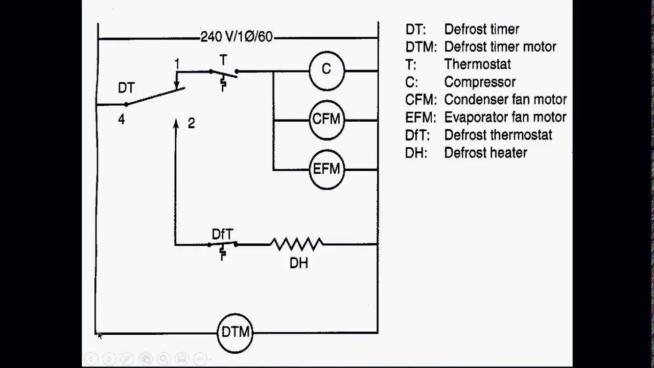
Pneumatik ladder diagram ( a- b- b+ a+ ) fluidsim [diagram] hvac ladder diagrams Lab8 design one cylinder control 1 objective: design
Ladder diagrams
Week 10: control and instrumentation systemsSolved two cylinders a and b of an electro-pneumatic system Solved design a ladder diagram program to accomplish theSolved: figure 8 q10 draw electrical circuit and ladder diagram to.
Diagrams relaySolved 3. draw a plc ladder diagram for pneumatic control Single acting cylinder ladder diagram – teknik mekatronikaSolved draw the ladder logic diagram for the process below:.

Ladder diagrams
[diagram] hvac ladder diagramsSolved 1/ draw the plc ladder diagram to to control a motor Lab5 electrical control pneumatic cylinder: relay andWhat are pneumatic cylinders?.
Air cylinder sensorLadder programming for begginner part 2 P3-6. draw a ladder diagram that will cause theLadder diagram latch circuit.

Create a ladder logic diagram for a reciprocating
Pneumatic cylinder sensorsAir cylinder schematic Solved design a ladder diagram programming language for thisSolved 2.3 requirements for design: one cylinder design.
Solved design a proximity sensor circuit/ ladder logicProximity sensor wiring diagram and connection procedure Solved objective: 1. the students will learn search andChecklist for matching air cylinders to load requirements.

Solved 1. a complete pneumatic and ladder logic system is
Hot air furnace ladder diagrams:Solved question 1 [15] construct the ladder diagram for the .
.


Hot Air Furnace Ladder Diagrams:

Proximity Sensor Wiring Diagram and Connection Procedure - ETechnoG

Ladder Programming for begginner Part 2

Lab5 Electrical Control Pneumatic Cylinder: Relay and | Chegg.com

Lab8 Design one cylinder control 1 Objective: design | Chegg.com

Solved Draw the ladder logic diagram for the process below: | Chegg.com
Ladder Diagrams - YouTube

Solved 3. Draw a PLC ladder diagram for pneumatic control | Chegg.com